





Data Centre Network Migration: From Legacy Layer-2 to SONiC-Based L2 Leaf-Spine with MCLAG
 April 10, 2026
 ONES & SONiC
Executive Summary
This paper describes a real-world data centre network migration from a traditional Layer-2–only architecture based on Spanning Tree Protocol (STP) to a modern Leaf–Spine design using SONiC Network Operating System (NOS). The legacy environment relied heavily on VLANs and trunking, which introduced scalability limitations, blocked links, and operational complexity.
As part of the migration, we deployed a Layer-2 Leaf–Spine (L2LS) fabric with Multi-Chassis Link Aggregation (MCLAG) for server connectivity. This design eliminated STP from the data plane, enabled active-active server uplinks, improved link utilisation, and simplified failure handling. SONiC NOS was selected to provide an open, modular, and hardware-agnostic network operating system aligned with long-term scalability and automation goals.
1. Legacy Network Overview and Challenges
1.1 Legacy Architecture
The original data centre network was built as a pure Layer-2 environment with the following characteristics:
- Spanning Tree Protocol (STP) for loop prevention
- Extensive use of VLANs across multiple switches
- Trunk links between the aggregation and access layers
- Single-homed or active-standby server connections
While this design was functional, it was increasingly difficult to scale and operate reliably.
1.2 Key Challenges Observed
- STP convergence delays:Topology changes resulted in traffic disruption during reconvergence
- Blocked links: :STP disabled redundant paths, leading to inefficient bandwidth utilisation
- Operational complexity:Troubleshooting MAC learning, loops, and intermittent traffic drops was time-consuming
- Limited scalability:VLAN sprawl and broadcast domains restricted horizontal growth
These challenges motivated a redesign toward a more deterministic and scalable architecture.
2. Design Goals and Migration Drivers
Before selecting the target architecture, the following design goals were defined:
| Design Goal | Requirement |
|---|---|
| Remove STP dependency | Loop-free topology without a spanning tree |
| Improve link utilisation | Active-active forwarding |
| High availability | Dual-homed server connectivity |
| Operational simplicity | Predictable failure behaviour |
| Future readiness | Path to L3 / EVPN-based designs |
These goals directly influenced the choice of a Leaf–Spine topology with MCLAG and SONiC NOS.
3. Target Architecture Overview (L2 Leaf–Spine)
The new design is based on a Layer-2 Leaf–Spine (L2LS) architecture:
- Spine switches: Provide a non-blocking Layer-2 fabric between leaf switches
- Leaf switches: Connect servers and form MCLAG pairs at the access layer
- Server connectivity: Dual-homed to two leaf switches using port-channels
This architecture ensures full bandwidth utilisation while maintaining Layer-2 adjacency for existing workloads that require it.
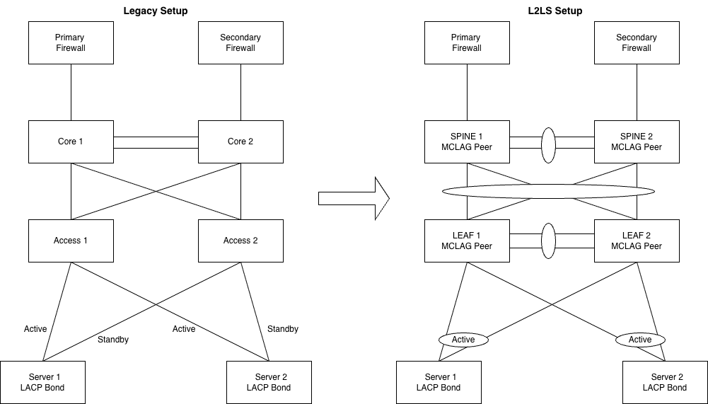
Figure 1: Target Leaf–Spine L2 Architecture with MCLAG (Topology Diagram)
3.1 Layer-3 Gateway and Firewall Integration
In this design, the SONiC leaf–spine fabric operates purely as a Layer-2 switching domain
The default gateway and Layer-3 termination are intentionally placed on the firewall device. This approach allows the existing security policies, NAT rules, and routing logic to remain unchanged during the migration.
All server VLANs are extended across the SONiC leaf switches using MCLAG, while the firewall continues to provide:
- Layer-3 gateway functionality
- Inter-VLAN routing
- Security policy enforcement
- NAT and inspection policies
By maintaining Layer-3 termination on the firewall, the migration avoids changes to the existing security architecture and routing policies, ensuring minimal disruption to production workloads.
4. Why SONiC NOS
SONiC NOS was selected based on the following technical considerations:
- Open-source, vendor-neutral network operating system
- Modular architecture with independent services
- FRRouting (FRR) integration for control-plane protocols
- Hardware abstraction via SAI, enabling platform flexibility
- Automation-friendly via CLI, REST, and telemetry interfaces
Rather than introducing proprietary dependencies, SONiC allowed us to align the network with modern DevOps and automation practices.
5. MCLAG Design and Control Plane Behaviour
5.1 MCLAG Overview
MCLAG enables a server to form a single logical port-channel across two physical leaf switches.
Key components include:
- Peer-link: Synchronises MAC, VLAN, and forwarding state
- Keepalive link:Detects peer failure
5.2 Failure Scenarios
The design was validated against common failure cases:
- Leaf switch failure
- Peer-link failure
- Server NIC or cable failure
In all scenarios, traffic convergence was deterministic and did not rely on STP recalculation.
6. Configuration Highlights (SONiC)
In this section, we configure the MCLAG domain on both peer switches. The configuration includes:
- Creating the MCLAG domain
- Setting the system MAC address
- Configuring the unique IP using VLAN4094
- Adding member PortChannels
- Configuring the keepalive link
6.1 MCLAG Peer Configuration (Example)
This configuration establishes the MCLAG control-plane relationship between leaf peers.
6.2 Server Port-Channel Configuration
Each server-facing port-channel is mapped consistently across both leaf switches .
7. Migration Strategy and Execution
A "Big Bang" migration was deemed too risky. We adopted a parallel build approach.
- Physical Build: New SONiC Spine and Leaf switches racked and cabled alongside existing legacy gear
- L2 Bridge: A temporary high-bandwidth trunk was established between the Legacy Core and the new SONiC Spines. This extended the L2 domain, allowing seamless VM migration.
- Host Migration: Servers were migrated rack-by-rack. This involved moving cables from Legacy Access switches to SONiC Leaf switches and updating the server-side bonding config to LACP (802.3ad).
- Validation: After each batch, we verified connectivity and application health.
- Decommission: Once all hosts were moved, the bridge link was severed, and legacy hardware was powered down.
8. Operational Benefits Observed
Post-migration, the following improvements were observed:
- Complete removal of STP events
- Improved bandwidth utilisation via active-active links
- Faster failure convergence
- Simplified troubleshooting and visibility
Operational overhead was significantly reduced compared to the legacy design.
9. Challenges and Lessons Learned
- Initial learning curve with SONiC architecture and service model
- Importance of strict configuration consistency across MCLAG peers
- Need for clear operational runbooks for failure scenarios
These lessons informed internal best practices and future designs.
10. Future Roadmap
The current L2LS design provides a strong foundation for future enhancements, including: :
- Transition to Layer-3 underlay
- EVPN/VXLAN-based overlays
- Increased automation and telemetry
Conclusion
Migrating from a legacy Layer-2 STP-based network to a SONiC-powered Leaf–Spine architecture with MCLAG significantly improved scalability, reliability, and operational efficiency. This design removed long-standing limitations while preparing the data centre for future growth and modernisation
Connect with Aviz experts to validate your SONiC Leaf–Spine design and plan your next steps toward a scalable, future-ready architecture.
1. Why was the legacy Layer-2 STP-based network replaced?
The legacy design relied on Spanning Tree Protocol, which caused blocked links, slow convergence, operational complexity, and limited scalability. As the data center grew, these issues made the network harder to operate and less predictable.
2. What problems did Spanning Tree Protocol create in the data center?
STP introduced convergence delays during topology changes, blocked redundant links that wasted bandwidth, and made troubleshooting MAC learning and intermittent traffic issues time-consuming and complex.
3. What architecture replaced the legacy Layer-2 network?
The legacy network was replaced with a Layer-2 Leaf–Spine (L2LS) architecture using MCLAG, which eliminated STP from the data plane and enabled active-active forwarding across all links.
4. Why was a Leaf–Spine design chosen for this migration?
Leaf–Spine provides predictable traffic patterns, full bandwidth utilization, and horizontal scalability. It simplifies failure behavior and removes the dependency on STP while maintaining Layer-2 adjacency for existing workloads.
5. What role does MCLAG play in the new design?
MCLAG allows servers to connect to two leaf switches using a single logical port-channel. This enables active-active server uplinks, improves availability, and ensures deterministic traffic convergence during failures.
6. Why was SONiC selected as the network operating system?
SONiC was chosen for its open, vendor-neutral architecture, modular service model, hardware abstraction, and strong support for automation and modern operational workflows.
7. Why was Layer-3 gateway functionality kept on the firewall?
Keeping Layer-3 termination on the firewall allowed existing routing, NAT, and security policies to remain unchanged. This reduced migration risk and minimized disruption to production workloads.
8. How was the migration executed without major downtime?
A parallel build and migration approach was used. The new fabric was deployed alongside the legacy network, connected via a temporary L2 bridge, and servers were migrated rack-by-rack with validation at each step.
9. What operational improvements were observed after the migration?
Post-migration, STP events were eliminated, link utilization improved through active-active paths, failure convergence became faster and predictable, and overall troubleshooting and operational overhead were reduced.
10. How does the SONiC-based L2 Leaf–Spine design prepare the data center for the future?
It provides a clear path to Layer-3 underlays, EVPN/VXLAN overlays, and increased automation. This enables scalable growth, modern telemetry, and long-term operational flexibility.


